Creating a null modem cable for the Alphatronic
Introduction
Having an old computer there is always the question “how to connect to it?”. The Alphatronic computer has a serial connector (actually it has two). The one serial connector I’m going to use, was intended to be used by a printer. But since it is just a serial connection, anything can be attached there and not just a printer. Besides that, I don’t have a printer from the old days, that would work here.
With such a connection, some easy things are possible: The MOS (like the BIOS) has the ability to copy every output of the screen to the printer port. This can be used to print the screen. In my case, I’ll print the screen to a file. That way, I can e.g. create a backup of the BASIC programs by just listing the program. It is essentially like recording the session. Under Linux, you would use the script utility.
Usually you would just buy an ordinary serial null modem cable, but finding one with a 25-pin male header on one side and a 9-pin female header on the other side turned out not to be so easy. The Alphatronic has the 25-pin port and a USB-to-serial adapter usually has a 9-pin port. There are straight cables available for 9/9 and you can combine various adapters for 25/9-pins. In the end, it’s still fun to build your own cable.
Building the cable
First you need to order some parts. You’ll need
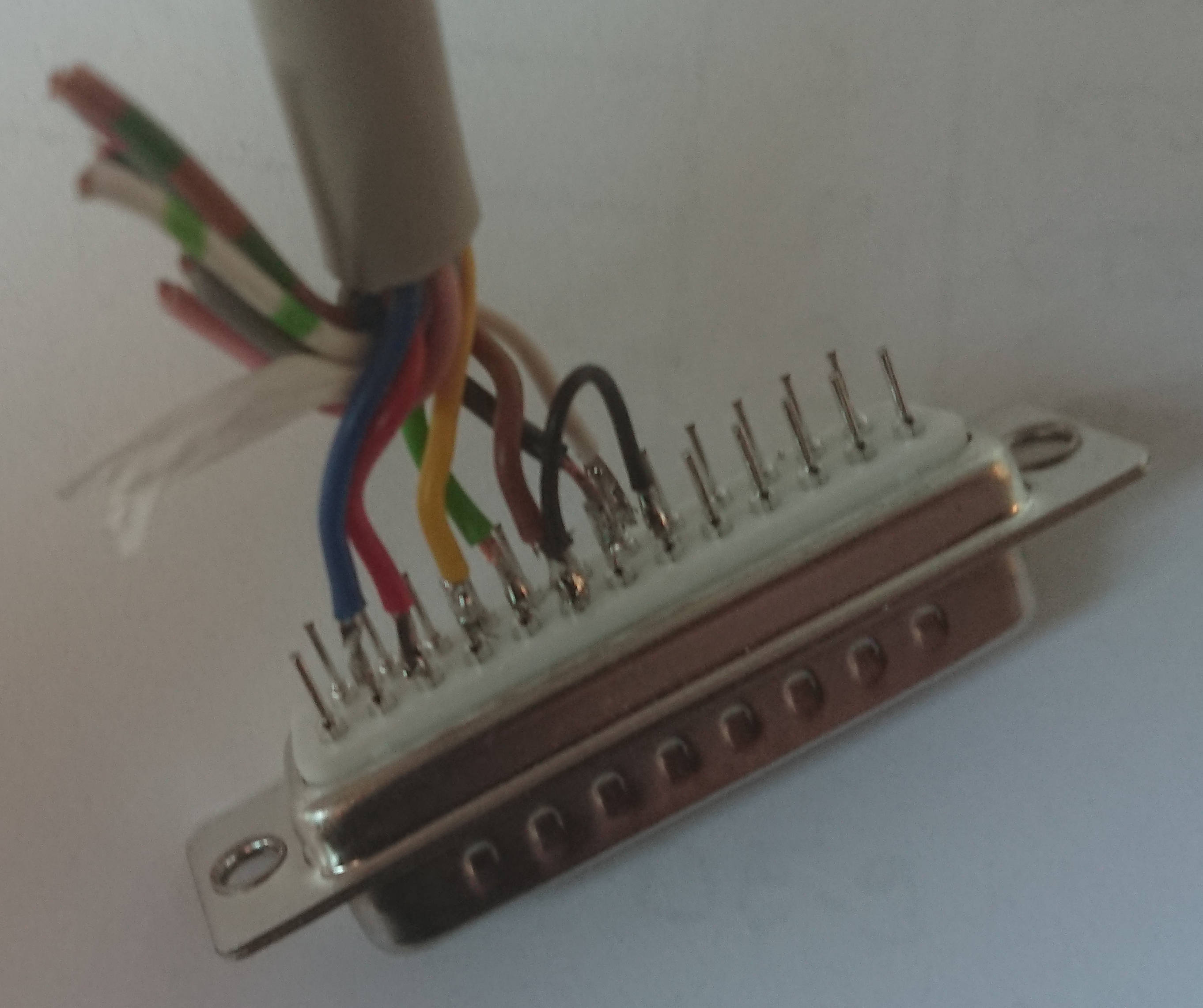
- DB-25 male connector (plug). It has 25 pins.
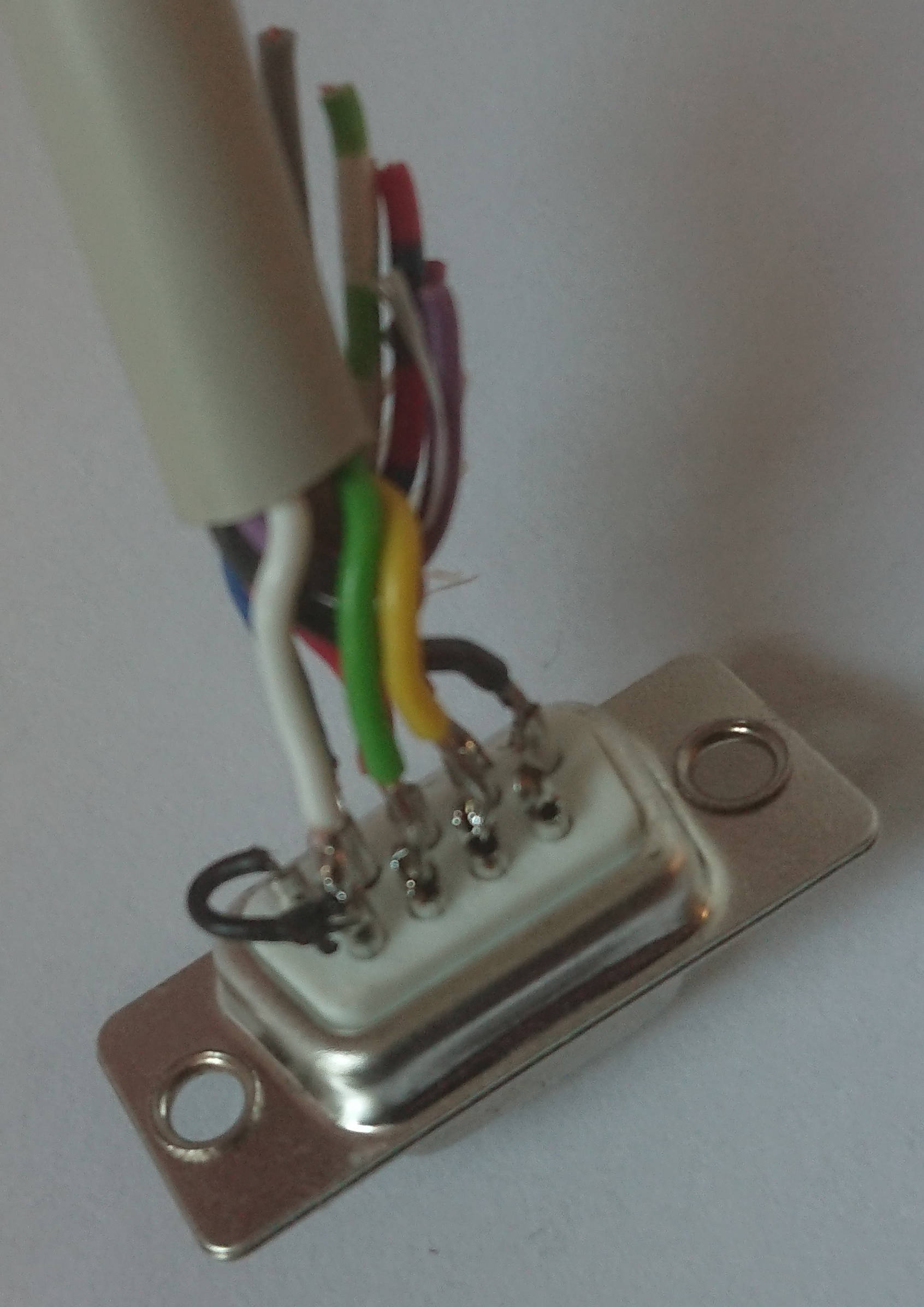
- DE-9 female connector (port). It has 9 pins.
- a data cable with at least 7 signal cables.
Then you need to think about the wiring diagrams of a Null modem cable. Here’s the one I used:
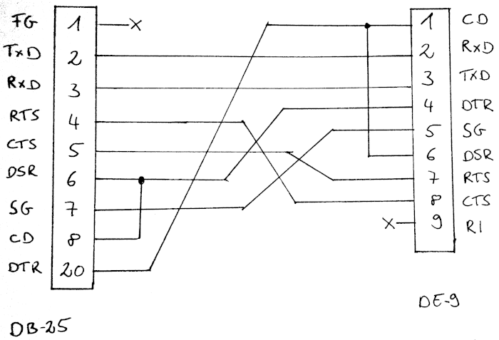
Or in the tabular form - including the (my) signal cable colors:
| DB-25 | DE-9 | Color | ||
|---|---|---|---|---|
| Pin | Signal | Signal | Pin | |
| 2 | TxD | RxD | 2 | blue |
| 3 | RxD | TxD | 3 | red |
| 4 | RTS | CTS | 8 | yellow |
| 5 | CTS | RTS | 7 | green |
| 6 | DSR | DTR | 4 | brown |
| 7 | SG | SG | 5 | black |
| 20 | DTR | DSR | 6 | white |
As you see, the signal TxD on the one side is connected to the signal RxD on the other side, which makes this a null modem (crossover) cable. The same is done with the signals RTS/CTS and DSR/DTR.
You can see, that at least 7 signal cables are needed.
For reference, here’s the printer port spec from Alphatronic’s manual:
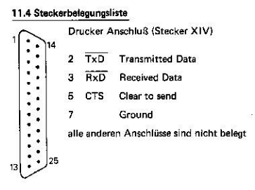
So, we would only have needed 3 signals to get it working. Our cable is now more complete. And luckily, Alphatronic complies to the standard, so the cable should work.
Testing
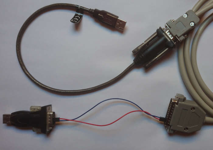
You can test the null modem cable with one PC. You need however two serial ports. I used two USB-to-serial adapters.
- Connect the cable with one usb adapter. This is probably the 9-pin side.
- Use a wire to connect pin 3 of the DB-25 connector (RxD) with pin 2 of the DE-9 connector (RxD). Since our cable already does the crossing once, we don’t need to do it here again.
- Use another wire to connect pin 2 of the DB-25 connector (TxD) with pin 3 of the DE-9 connector (TxD).
Now plug in the USB adapter and test the connection:
cat -v /dev/ttyUSB0 &
echo "Test" > /dev/ttyUSB1
kill %-
We are reading from one serial port and sending some data to the other. We should see the data, as it is looped back through the cable.
Now the other way round:
cat -v /dev/ttyUSB1 &
echo "Test other direction" > /dev/ttyUSB0
kill %-
You can issue multiple echos before killing the background cat.
You can also use cutecom, which is a easy to use graphical serial terminal. Just run it twice and connect to each port.
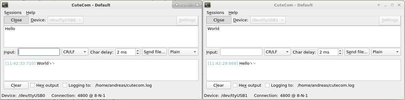
Here’s photo of my test setting:
Using the cable with the Alphatronic
The last step is ensuring, the cable can be used as intended:
- Start the Alphatronic
- In the MOS, before you boot from a floppy, enter first
PP. This initializes the printer port with the default settings. The default settings are described in the MOS manual, available from Geschichte Alphatronic P2 und der SKS. A more detailed description is available from Computermuseum der Information Universität Stuttgart. On their ftp server, they collected manuals: ftp://computermuseum.informatik.uni-stuttgart.de/alphatronic/. One is the “Alphatronic Systemhandbuch”. Look up the description for “P” (Preset Device). The default settings for the printer port are: 4800@8N1. The commandPPis equivalent toPP1E05,0129,0. You could change it to a higher speed of 9600 baud withPP1E05,0112,0. - Then enter
L. This enables the redirect of all output, that goes to the screen, to go to the printer as well. - Boot from floppy as usual.
The session recording on the printer then starts with the boot command:
.B
.I4000 B18B
.U4000 FC00
Memory size?
How many disk drives? 2
How many files(0-15)?
Basic Rev. 3.00/D/E/3
Copyright (C) 1981 by T A
19165 Bytes free
Ok
LIST
Ok
MOUNT 1
Ok
FILES
EKA    EUR 8    17+4       7    AUTOLO.AD  4    BULLE  KUH 4    KALEND ER  2
MAZE       5    BIER       4    EKA        2    SPIELE     2    MUSIK      1
LIED  .1   4    DISK       1    LIED   W   7    SMP        2    LIED   2   7
MASTER     6    RECHEN     5    LIED   3   4    DISK2 .    1    DISK2  A   1
MEM   .DMP 1    LIED  .W2  7
Ok
RUN "SMP"
##################################################################
##                                                              ##
##                    Start --- Men} --- Programm               ##
##                                                              ##
##################################################################


1................Rechen...........................................
2................Rechner..........................................
3................Spiele...........................................
4................Musik............................................
5................Erdkunde.........................................
6................System-Ende......................................


Welche Option? 2
File not found in 180
Ok
remove 1
Ok
FILES
Disk not mounted
Ok
Comments
No comments yet.Leave a comment
Your email address will not be published. Required fields are marked *. All comments are held for moderation to avoid spam and abuse.