Alphatronic P2 speed follow-up
As described in the last post Intel 8085A timings it has been established that it is very likely, that the Alphatronic P2 introduces a wait state for accessing RAM and ROM. The numbers seem to fit.
Adjusted BASIC program
Adjusting the BASIC program from Measuring Floppy Drive rotation speed - Part 2
using 290 LPS=78947! 'loops per second: 3MHz/38 cycles - dur. of one loop (38 cycles instead of 29 cycles), gives the
following result:
RUN
In the last used drive a floppy has to be inserted!
How many measurements should be taken? 10
    result: 0 -> 16217
    result: 1 -> 16218
    result: 2 -> 16218
    result: 3 -> 16217
    result: 4 -> 16217
    result: 5 -> 16218
    result: 6 -> 16217
    result: 7 -> 16218
    result: 8 -> 16217
    result: 9 -> 16217
Data ready
  Minimum: .205416 s
  Maximum: .205429 s
     Mean: .205421 s
Rotations: 292 rpm
 Accuracy: .0126667 ms
Ok
So, now the RPM actually is a bit too low. The floppy drive in this run was the GoTek Floppy Drive Emulator which I verified with an oscilloscope to have an index signal exactly every 200ms, which would then be 300 rpm. But to be exact: The BASIC/machine program doesn’t measure the index signal from the floppy drive directly it busy checks the floppy controller, so there could be some delay. You can see however, that the counter is pretty stable it’s just +/- 1 (lowest is 16217, highest ist 16218).
I also ran it against the second real floppy drive with the following result:
RUN
In the last used drive a floppy has to be inserted!
How many measurements should be taken? 10
    result: 0 -> 16034
    result: 1 -> 16062
    result: 2 -> 16067
    result: 3 -> 16066
    result: 4 -> 16049
    result: 5 -> 16014
    result: 6 -> 15996
    result: 7 -> 16011
    result: 8 -> 16066
    result: 9 -> 16060
Data ready
  Minimum: .202617 s
  Maximum: .203516 s
     Mean: .203206 s
Rotations: 295 rpm
 Accuracy: .899338 ms
Ok
The real floppy drive ends up with 295 rpm. Comparing this to the emulated floppy, this means that the floppy drive probably runs a tiny bit too fast.
Tone generator V3
I’ve also updated the tone generator program described in Measuring CPU speed. The loop counter is a bit smaller to adjust for the cpu cycles in WAIT state.
100 PRINT"Tone Generator V3"
110 CLEAR ,&HF000
120 I=&HF000
130   READ D$
140   D=VAL("&H"+D$)
150   IF D>255 THEN GOTO 500
160   POKE I,D
170   I=I+1
180 GOTO 130
200 DATA 06,05,0E,DC,3E,01,D3,12,16,BC,15,C2,0A,F0,3E,00,D3,12
210 DATA 16,BC,15,C2,14,F0,0D,C2,04,F0,0E,DC,3E,00,D3,12,16,BC
220 DATA 15,C2,24,F0,3E,00,D3,12,16,BC,15,C2,2E,F0,0D,C2,1E,F0
230 DATA 05,C2,02,F0,C9
240 DATA E0F
500 I=&HF000
510 CALL I
The difference is that instead of repeating the loop 243 (0xF3) times, it should only be repeated 188 (0xBC) times, so that half a second is gone.
The resulting video:
Looking at the audio stream with Audacity, we see, that the period is 1.006s. This is now pretty close to what it is supposed to be.
Boards
Looking at the PCBs of the Alphatronic P2, I could identify the Intel/AMD 8085A CPU and also the READY signal (pin 35). However, following the traces resulted in nothing. It is indeed connected to the MC-80 bus in the backplane. But no other card connects to this signal. Traces that are visible with the naked eye are not existing. Maybe the PCB is a multilayer.
The ICs that are used for provided the ROM are 2716 (Texas Instruments), which is a “2048 x 8 erasable ROM”. We got 3 of these on the CPU PCB, which gives room for a 6kB firmware. This is probably the MOS (Mikrocomputer-Operating-System) which is mapped from 0x0000 to 0x2FFF. Not everything is usable in this area, since 1k of RAM is mapped from 0x1800 to 0x1BFF (and 0x1C00 to 0x1FFF is unusable).
So the ROM chips have the following exact label: “TMS2716C”. These are all manufactured by Motorola in the year 1981 and 1982. The C-suffix indicates that it uses a “frit-seal package” as described in Glass frit bonding. The chips have a window for erasing via UV light.
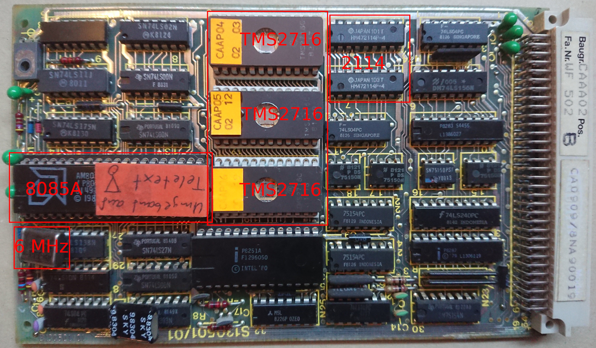
There are two variants of the chip TMS27A16 and TMS2716. The A-variant is faster, it has a maximum access time of 300ns. The chip used in the Alphatronic is TMS2716 and has a maximum access time of 450ns. This is 10ns faster than the maximum time the 8085A demands for the time “ALE to Valid Data” which is 460ns. That’s only a window of 10ns in the worst case. Not sure if that would be a stable operation without a wait state.
The 1k RAM on the CPU PCB is a 2114 (Intel). Actually there are two chips labeled with “HM472114-P4” which are manufactured by Hitachi. These are actually two “1024-word x 4-bit Static Random Access Memory”. The access time according to the datasheet is 450ns (for the “-4”-variant). So, it’s the same max access time as for the ROM chips.
Both chips (RAM and ROM) also need some time from chip select to data ready, which could also be the reason to insert a wait state.
Conclusion
I guess, in order to have a definitive answer to this, I would need to use a logic analyzer and check the signals of 8085A to be sure, what is actually happening here. Then I could see what the CPU is doing while executing my programs.
Comments
No comments yet.Leave a comment
Your email address will not be published. Required fields are marked *. All comments are held for moderation to avoid spam and abuse.