Running a program from VRAM
- Introduction
- The video controller
- More detailed information
- The adjusted machine code for “read_index_duration”
- The adjusted BASIC program
- Result
Introduction
While experimenting with the memory switch I’ve seen, that the video RAM
is mapped at 0x3000. From the perspective of the CPU, it is just ordinary memory. But in reality, it is memory
on a different card. Why not run my program in this memory area? Would be interesting to see, how fast or slow
it is executed there. What could possibly go wrong?
The video controller
The alpatronic uses a CRT-5037 chip for the video controller. On the card, there are 4 chips of type “HM472114P-4”. These are “1024-word x 4-bit Static Random Access Memory” chips. In total, there is 2kB of VRAM on this card. Plenty of space for my own program.
Since it’s static RAM, it doesn’t do refresh cycles and maybe the CPU doesn’t need to wait. But it’s RAM, that is used concurrently by the CPU and by the CRT-5037. This might give some delays…
The card has also an EEPROM on board. In this ROM the characters are stored. The video controller reads the data from the RAM, which serves as the frame buffer, combines each character found there with the information from the ROM and produces a video signal, that a CRT monitor can display. The alphatronic uses a composite signal. The card has more chips on it, probably for address decoding and chip selection.
More detailed information
On the webpage Geschichte alphaTronic P2 und der SKS (history of alphaTronic P2
and SKS) there is also the system documentation for
the video controller. See the link for “SKS_BC10_Alphatronic P2 Displaycontroller”. It contains valueable information.
E.g. the memory location 0x3000 could be changed to 0x7000 or 0xF000 depending on some solder bridges.
It maps actually 4kB of memory although there is only 2kB on the card. This is to make it easier to address
columns and rows. The adress decoder on the card will the map these addresses to the correct locations
on the static RAM. 4k is 4096 or 12 bits. The lower 7 bits address the column (0..127) and the remaining 5 bits
address the row (31). In other words, to change column 10 in row 12, you’ll need to write to address
0x360A (in case 0x3000 is the base address). These 12 bits are further mapped down to the 11 bits of
the VRAM. There is a whole table that describes the mapping, but we anyway have only access through the
bus addresses and not directly to the VRAM.
Another interesting sentence is explaining the interrupt request: it is part of a “forbidden memory area” and it is used to synchronize access from CPU. This access should only happen during the vertical blanking interval. This is to avoid any distortions. That’s a very interesting information. How long is this interval? The monitor overall needs to mainain a refresh rate. This is often (at least in Europe) 50 Hz. That’s also called the vertical frequency. This means, every 20ms our CPU has the change to access the VRAM. It needs to access the VRAM in order to run the instructions from there. But how long does it have time to do so?
From the previous posts, we know that we hear the monitor beeping at around 15kHz. This is the “line frequency”, which is typical for PAL: PAL has 625 lines at 25 frames per second. These 625 lines are split up into two fields and displayed at 50 frames per second. This is the so called “interlaced mode”. So we have 625/2=312.5 lines 50 times a second. This gives 15625 Hz. And that’s what’s defined on the specification for the monitor as “horizontal frequency”:
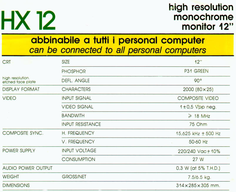
That’s of course only the monitor. Time to look a bit closer at the signal. Every line has a specific length in
microseconds, so that we can maintain 312.5 lines in 20ms (50Hz). Taking these numbers and calculating
0.020s / 312.5 is exactly 64µs. That’s the duration of one line. Every 64µs there will be a horizontal
sync signal. But for one line, only part of the 64µs line signal is actually displayed. There is a
“front porch” before the horizontal sync signal, the sync signal itself has some duration and there is a
“back porch” after the sync signal and just before the actual line data (active video). On the Wikipedia page
for PAL - Signal Details the actual numbers are presented.
It turns out, that the horizontal blanking internal is around 12µs long. During that time, the cathode ray tube
beam needs to go from the right all back to the left border of the screen. This has to happen within 12µs.
During that time, the beam is off - it’s blank. Otherwise you would see the beam going back. With the help
of the horizontal sync signal, the movement of the beam is synchronized so that the active video data of a line
appears on screen and the front porch, sync and back porch are not visible and off screen.
After 312.5 lines have been drawn, the beam is now at the bottom line and in order to draw the next (half) frame, it needs to go back to the top left position. But this time, the distance is bigger so 12µs are not enough time. To buy some time for this, not all of the 312.5 lines are actually visible. The beam is blanked a couple of lines before the last line and it is also not switched back on with the first line - a couple of lines at the beginning are also off screen. During that time (the vertical blanking interval) the beam moves from bottom right to top left. But the video signal keeps on ticking every 64µs a new line… but without real data just to fill the gaps. These lines are not displayed on screen, but they can still be used for some useful things like videotext. Similar to the horizontal blanking interval, the vertical blanking interval is also split into a front porch, sync signal duration and back porch. However, the duration is now measured in units of lines. From the 312.5 lines only 288 lines are visible. So 24.5 lines are the total duration of the vertical blanking interval. This is exactly 1.568ms.
To verify some of the numbers, let’s have a look at the video controller CRT-5037 datasheet. Unfortunately this controller is very flexible and the timings can be programmed. E.g. the front porch and back porch durations can be programmed in terms of “character times”. You configure a specific screen size, let’s say 80 characters and 24 rows. It supports up to 64 rows. There is one fixed time specified, that is the vertical sync width, which is always 3 lines (192µs). Ok, this was not so helpful.
But even if the numbers are not completely valid, the vertical blanking interval is around 1.6ms.
That means that every 20ms the CPU can access the VRAM for less than 1.6ms. That’s not much time.
During 1.6ms there are 4800 clock cycles (or T-states) at 3MHz. Our loop to check the index signal of the floppy
drive (“read_index_duration”) takes 29 cycles (without wait states). That would increase our counter
by 4800/29=165. The floppy takes 200ms for one rotation. We have during one rotation the change
to execute the code 10 times. So the counter, I print out at the end, is probably around 1650.
And if I calculate that back to the floppy’s rpm value: 3761rpm… almost at hard drive speed.
So, my prediction is, that the basic program prints out at the end a floppy rotation speed of 3761rpm or even bigger. We’ll see what it is when I run the following program for real.
The adjusted machine code for “read_index_duration”
                                       ORG     3000H
                                       PUBLIC  READ_INDEX_DURATION
3000'  3E D4      READ_INDEX_DURATION: MVI     A,D4H    ;FORCE-INTERRUPT command with IP (index pulse)
3002'  D3 50                           OUT     50H      ;execute command
3004'  06 40                           MVI     B,40H    ;Mask for index detected flag in status register
3006'  11 0000                         LXI     D,0      ;init counter in D
3009'  DB 50                           IN      50H      ;reading the command register?? apparently clearing the IRQ flag
300B'  DB 54                   LOOP1:  IN      54H      ;reading status register into A
300D'  A0                              ANA     B        ;check if index is set
300E'  CA 0B30'                        JZ      LOOP1    ;if no index yet, busy wait...
3011'  DB 50                           IN      50H      ;clearing the INDEX flag for next index detection
3013'  13                      LOOP2:  INX     D        ;counting now...
3014'  DB 54                           IN      54H      ;reading status register into A
3016'  A0                              ANA     B        ;check if index is set
3017'  CA 1330'                        JZ      LOOP2    ;jump back, if no index and keep counting
301A'  73                              MOV     M,E      ;copy counter (low Byte) to memory at [H]
301B'  23                              INX     H        ;
301C'  72                              MOV     M,D      ;copy counter (high Byte) to memory at [H]
301D'  C9                              RET
The adjusted BASIC program
Since I use the VRAM to run the program, I’ll try to avoid printing something while the program is running. Otherwise I might overwrite my program in VRAM. So there is no status update after each measurement.
100 '************** DRIVEROT7
110 CLEAR , &HFF00
120 DEFINT D
170 PRINT"In the last used drive a floppy has to be inserted!"
180 INPUT"How many measurements should be taken"; COUNT
190 DIM DAT%(COUNT)
195 GOSUB 700 ' install read_index_duration into 3000H
200 FOR D=0 TO COUNT-1
220     CALL RID(LOOPS%)
230     DAT%(D)=LOOPS%
250 NEXT
260 PRINT"Data ready"
270 MIN=DAT(0) :MAX=MIN :SUM=0
280 FOR D=0 TO COUNT-1
290     IF DAT(D)<MIN THEN MIN=DAT(D)
300     IF DAT(D)>MAX THEN MAX=DAT(D)
310     SUM=SUM+DAT(D)
315     PRINT"    result:";D;"->";DAT%(D)
320 NEXT
330 MEAN=SUM/COUNT
340 LPS=103448! 'loops per second: 3 MHz/29 cycles - dur. of one loop
350 RPM=INT(60*LPS/MEAN+.5)
360 DIF=MAX-MIN
370 PRINT"  Minimum:";MIN/LPS;"s"
380 PRINT"  Maximum:";MAX/LPS;"s"
390 PRINT"     Mean:";MEAN/LPS;"s"
400 PRINT"Rotations:";RPM;"rpm"
410 PRINT" Accuracy:";DIF*1000/LPS;"ms"
420 END
450 ' install loop
460     READ D$
470     D=VAL("&H"+D$)
480     IF D>255 THEN RETURN
490     POKE I,D : I=I+1
495 GOTO 450
700 ' install read_index_duration into 3000H
710 I=&H3000 : RID=&H3000
720 GOTO 450
730 DATA 3E,D4,D3,50,06,40,11,00,00,DB,50,DB,54
740 DATA A0,CA,0B,30,DB,50,13,DB,54,A0,CA,13,30
750 DATA 73,23,72,C9,E0F
Result
I’ve recorded the running program in a video, since there is something interesting to see:
I repeated the measurement 10 times, and during that time there are visible distortions on the screen. It seems, that the video card and the CPU fight for access to the VRAM.
But you can indeed see the program now, since the video controller shows the VRAM which constains the program:
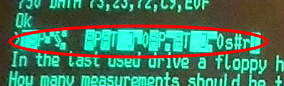
Surprising however are the numbers itself:
In the last used drive a floppy has to be inserted!
How many measurements should be taken? 10
Data ready
      result: 0 -> 20001
      result: 1 -> 20002
      result: 2 -> 20002
      result: 3 -> 20002
      result: 4 -> 20002
      result: 5 -> 20001
      result: 6 -> 20002
      result: 7 -> 20002
      result: 8 -> 20002
      result: 9 -> 20002
  Minimum: .193344 s
  Maximum: .193353 s
     Mean: .193351 s
Rotations: 310 rpm
 Accuracy: 9.66669E-03 ms
Ok
This means, that the VRAM access is as fast as static RAM! While it doesn’t make much sense to run everything in VRAM now it’s still interesting to see, that VRAM appears to the CPU as an ordinary memory (it’s just memory mapped). It can access it also for running instructions from it.
I was also wrong with my prediction, that it would be slower. Maybe only write access is blocked so that it occurs only during the vertical blank time? But reading from VRAM also seems to interfere with the normal operation of the video controller which also constantly reads from VRAM.
Comments
No comments yet.Leave a comment
Your email address will not be published. Required fields are marked *. All comments are held for moderation to avoid spam and abuse.