Measuring CPU speed
- Previously on …
- Error?
- Alternative measurement with sound
- The program
- Results
- Measuring time?
- Summary
Previously on …
In the previous posts I tried to measure the floppy drive rotation speed. It all started with a sample BASIC / assembler program I found in one book. The full program is described in Measuring Floppy Drive rotation speed. It uses the track 0 signal of the floppy disk controller and measures the time between two consecutive track 0 signals. The time is measured simply by a counter. This gave a surprising result of about 390 rpm. This is too much.
I went on to explore alternative ways for measuring the drive rotation speed. In Measuring Floppy Drive rotation speed - Part 2 I tried to improve the program mostly by disabling interrupts. I thought that maybe concurrently occuring interrupts could have a negative impact on the measuring. But the result stayed nearly the same. Accoding to this program, the floppy drive spins the disks at 388 rpm. Still too much.
Next method described in Measuring Floppy Drive rotation speed - Part 3 was to use stroboscope light and a pattern on the spindle wheel. This method has some disadvantages: You need to demount the drive and run it outside of the computer. You mabye get a different results than operating the drive in situ. The other disadvantage is, that you only get a estimate and no exact number. The result is therefore a bit vague: “the drive speed is not perfectly in spec, but also not completely out of scope”.
The fourth method Measuring Floppy Drive rotation speed - Part 4 used a oszilloscope to directly measure the index signal from the drive - while operating inside the computer. This lead to the result, that the drive rotates at about 303 rpm. This is really good in spec - it should actually rotate at 300 rpm, as it is a double density 5,25” drive. Meanwhile I connected also the GoTek Floppy Drive Emulator and measured the emulated floppy drive as well. It rotates exactly at 300 rpm. In the oszillosocpe I could also see the difference between the real floppy drive and the emulated: The real floppy drive drives the index signal slightly longer low than GoTek. Just out of interest I ran the program from part 2 against GoTek and I measured still 388 rpm.
The last method Measuring Floppy Drive rotation speed - Part 5 was just for fun and I did this also not on the real floppies. But I still wanted to describe this method, which uses the numerous available sensors in a modern smartphone - e.g. the accelerometer. With that you can directly measure the rotation speed - although in a different unit.
In summary:
| method | result | "error" |
|---|---|---|
| cpu counter 1 | 390 rpm | 29% |
| cpu counter 2 | 388 rpm | 28% |
| stroboscope pattern | not perfectly at 300rpm, but not completely out of scope neither | - |
| oscilloscope | 303 rpm | 0% |
Error?
So what about these 28% or 29% off? Where’s the error? I’ve counted the instructions and the cycles myself. Did I make an error there? Or doesn’t the CPU run at 3 MHz? If it would run slower, say at 2.34 MHz, then my calculations would result in 303 rpm…
But does the CPU run slower? I checked - there is indeed a 6 MHz quartz built in. The CPU runs at half the frequency of the crystal oscillator. That would mean, that the crystal would run slower as well - at 4.68 MHz instead of 6 MHz. This sounds unlikely. And if the CPU would run today slower than at manufacturing time, I would expect lots of timing problems. But as far as I see, there are no problems - even using the floppy drives is possible.
Alternative measurement with sound
What are my options here? How can I verify, whether the CPU runs indeed at 3 MHz?
I remembered, that the computer has a built-in buzzer that I can access. I know this, because it can Play Silent Night and other songs. Maybe if I generate a tone at exactly 440 Hz and then I can check it with a tuner and if everything is well, the tone should be at exact this frequency. So let’s do this.
It was a funny experience to create a machine program manually without an assembler. You really need to do multiple passes to get the jump addresses correct and you need to lookup the actual opcodes… But it worked in the end. I know that the buzzer is connected at i/o port 0x12 and I can easily toggle it. In order to generate a tone at 440 Hz I need to switch the buzzer on half the time and switch it off again repeatedly. 440 Hz has a period of 1/440 seconds = 2.27ms. That means, I need to switch the buzzer on for 1.13ms and again off for the same amount. Assuming (!) that the CPU runs at 3 MHz, that means, I need to keep the buzzer on for 3409 cycles. In the end, I want to have the tone playing for 5 seconds. That means I need to repeat the on/off steps a couple of time. To be precise: 5000ms / 2.27ms = 2202 times.
The program
Here’s the pseudo code:
                            cycles per instruction
    mov b,2200              7+7
loop1:
    out x,1     ----+       10+7
    mov a,??        |       7 (maybe +7)
loop2:              | ON
    sub a,1         |       5 (dec)
    jnz loop2   ----+       10
    out x,0     ----+       10+7
    mov a,??        |       7 (maybe +7)
loop3:              |
    sub a,1         | OFF   5 (dec)
    jnz loop3       |       10
    dec b           |       5
    jnz loop1   ----+       10
We now need to determine the value of “a” that is used for the tight loops loop2 and loop3. Loop2 (and loop3) need
to consume 3409 cycles, the two instructions “dec” and “jnz” take together 15 cycles. That means “a=3409/15=227”.
That’s at least the order of magnitude for this number. Since we need to count the time starting after “out x,1”
the exact number would be: a = (3409 - 7 - 17)/15 = 225. Important is, that it’s within 8 bits.
Here’s the complete assembled program starting at offset 0xF000. It uses registers B+C for the outer loop1
and register E for the inner loops loop2 and loop3.
assembled program tone440
;address        machine code    mnemonic            clock cycles      comments
F000            06 08           MVI B, 8H           ; 7 cycles
F002            0E 98           MVI C, 98H          ; 7 cycles        (0x898 = 2200)
F004    loop1   3E 01           MVI A, 1            ; 7 cycles
F006            D3 12           OUT 12H             ; 10 cycles       (0x12 = 18)
F008            1E F2           MVI E, F2H          ; 7 cycles        (0xf2 = 242)
F00A    loop2   1D              DCR E               ; 4 cycles
F00B            C2 0A F0        JNZ F00AH           ; 7/10 cycles     (0xf00a --> loop2)
F00E            3E 00           MVI A, 0            ; 7 cycles
F010            D3 12           OUT 12H             ; 10 cycles       (0x12 = 18)
F012            1E EF           MVI E, EFH          ; 7 cycles        (0xef = 239)
F014    loop3   1D              DCR E               ; 4 cycles
F015            C2 14 F0        JNZ F014H           ; 7/10 cycles     (0xf014 --> loop3)
F018            0B              DCX B               ; 6 cycles
F019            3E FF           MVI A, FFH          ; 7 cycles
F01B            A0              ANA B               ; 4 cycles
F01C            CA 26 F0        JZ F026H            ; 7/10 cycles     (0xf026 --> end)
F01F            3E 00           MVI A, 00H          ; 7 cycles        (no-op for additional 7 cycles)
F021            A0              ANA B               ; 4 cycles        (no-op for additional 4 cycles)
F022            A0              ANA B               ; 4 cycles        (no-op for additional 4 cycles)
F023            C3 04 F0        JMP F004H           ; 10 cycles       (0xf004 --> loop1)
F026    end     3E FF           MVI A, FFH          ; 7 cycles
F028            A1              ANA C               ; 4 cycles
F029            C2 04 F0        JNZ F004H           ; 7/10 cycles     (0xf004 --> loop1)
F02C            C9              RET                 ; 10 cycles       (returns to BASIC)
| Instruction | Cycles (== machine cycle) | States (== clock cycle) | Page |
|---|---|---|---|
| ANA | 1 | 4 | 3-6 |
| DCR | 1 | 4 | 3-20 |
| DCX | 1 | 6 | 3-22 |
| JMP | 3 | 10 | 3-28 |
| JNZ | 2 or 3 | 7 or 10 | 3-29 |
| JZ | 2 or 3 | 7 or 10 | 3-32 |
| MVI | 2 | 7 | 3-37 |
| OUT | 3 | 10 | 3-41 |
| RET | 3 | 10 | 3-48 |
The clock cycles are taken from the assembly language programming manual. It’s important to differ between machine cycles and clock cycles. Clock cycles depend on the CPU speed, which is presumably 3 MHz for the 8085A in my Alphatronic P2. Let’s calculate once again the exact clock cycle count for the loops to determine the length:
At F004, we set the beeper output to high, this takes 7+10=17 cycles. At F008 the output is high and we need to start
counting: The MVI instruction takes 7 cycles, then DCR is 4 and as long as the register E was not decremented to
zero, we jump, which means, this takes 10 cycles. Except for the last loop iteration, then the JNZ takes only 7 cycles.
After that, we take the beeper to low, which takes additionally 7+10=17 cycles.
This gives us the time, the beeper is high (from F008 to F010 inclusive): 7 + (242-1)*(4+10)+4+7 + 7+10 = 3409 cycles.
And 3409 cycles @3MHz is: 3409/3000000s = 1.1363333ms which is the first half of 2.27ms which we need to create a 440Hz wave.
Let’s see, how long the beeper is low (from F012 to F023 and F006 inclusive):
7 + (239-1)*(4+10)+4+7 + 6+7+4+7 + 7+4+4+10 + 7+10 = 3416 cycles. And 3416 cycles @3MHz is: 3416/3000000s = 1.138667ms which
is the second half of 2.28ms which we need to create a 440Hz wave.
In total one period is 3409 + 3416 = 6825cycles which is 3000000Hz/6825 = 439.56 Hz. So according to this calculation, we
should be at most half a hertz off.
This period is now repeated 2200 times, which gives us approximately 2200 * 6825 = 1501500 cycles, which is 5.005 seconds.
The tone we hear, should be almost exactly 5 seconds long.
This assembler program cannot be run directly, we need to write a BASIC wrapper program around it. This puts the machine code
into memory using POKE and then calls the machine program:
The BASIC wrapper program
100 PRINT "Tone Generator 440Hz"
110 CLEAR,&HF000
120 I=&HF000
130   READ D$
140   D=VAL("&H"+D$)
150   IF D>255 THEN GOTO 300
160   POKE I,D
170   I=I+1
180 GOTO 130
200 DATA 06,08,0E,...
....
290 DATA E0F
300 I=&HF000
310 CALL I
Results
I’ve tried to verify the tone with a standard instrument tuner used by musicians, but this didn’t work. Apparently the Alphatronic is too loud: the fan of the power supply is running and also the floppy disks are running, which gives a good background noise. But I recorded a short video:
When analyzing the audio track with Audacity, we get the following FFT:
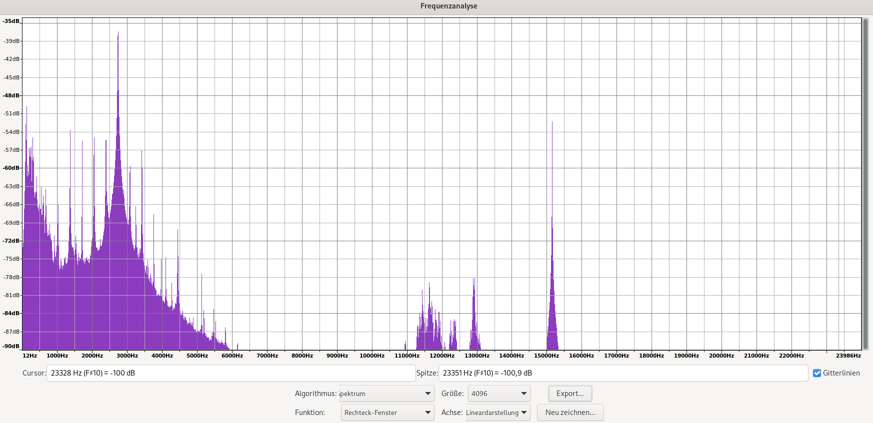
We don’t see a clear peak at around 440Hz, but we see definitive peak at 2736Hz. So, it’s probably some harmonic of our generated 440Hz. Which one? Maybe the sixth? Then we would have generated a tone at 456Hz. Or the seventh? Then our tone would be at 391Hz.
What we actually generate with this on/off beeper is a square wave and not a sinus wave. According to the theory of Square Wave it can be represented by odd harmonics which would be 3, 5, 7, 9, …. That would lead to the conclusion, that we generated a tone at 391Hz instead of 440Hz. With 391Hz our square wave period would be 2.56ms and the high (or low) duration would be 1.28ms instead of the anticipated 1.14ms. Maybe the CPU runs too slow?
The other peak you can see in the spectrum is at 15150Hz. This is maybe the line frequency of the monitor that is running at the same time. For PAL the line frequency is 15625Hz. Which is not exactly what I expected… but still within the specification of the monitor (+/- 500Hz).
I can’t really make a definitve conclusion here. I’d say, the result is inconclusive.
Measuring time?
But, there is another thing we can measure: time. I wrote the program, so that the tone would be generated exactly
5.05s long. Let’s see, how long it really was: If I select the waveform in Audicity, I get a length of “6.427s”.
That’s clear: It’s bigger than 5.05s. Comparing the numbers, we have a factor of 6.427s/5.05s = 1.27.
If we compare the rpm of the floppy measurements: 388rpm/300rpm = 1.29. The factor is very close. The 388rpm
were determined by a machine program as well. This looks like there is a systematic error when calculating
the duration of machine instructions. Either the clock cycle calculations are wrong or the CPU speed is indeed
different (slower) than the assumed 3MHz.
Just to be sure, I’ve created a second program, which plays 5 tones at 440Hz each 1 second long. So we have a pattern of 1 second tone, 1 second silence and so on. The assembly program is very similar, but the numbers are smaller, so we don’t need a 16bit register (B+C) anymore and can deal with 8bit values only. Instead of playing the tone 5 seconds, we play it only 0.5 seconds, so instead of 2200 loop iterations, we only have 220. But we add another loop around the whole program and repeat it 5 times.
assembled program tone440 v2
; address       machine code    mnemonic        comments
F000            06 05           MVI B, 5H
F002    G       0E DC           MVI C, DCH      ; 0xDC=220
F004    C       3E 01           MVI A, 1H
F006            D3 12           OUT 12H         ; 0x12=18
F008            16 F3           MVI D, F3H      ; 0xF3=243
F00A    A       15              DCR D
F00B            C2 0A F0        JNZ A           ; A -> 0xF00A
F00E            3E 00           MVI A, 0H
F010            D3 12           OUT 12H         ; 0x12=18
F012            16 F3           MVI D, F3H      ; 0xF3=243
F014    B       15              DCR D
F015            C2 14 F0        JNZ B           ; B -> 0xF014
F018            0D              DCR C
F019            C2 04 F0        JNZ C           ; C -> 0xF004
F01C            0E DC           MVI C, DCH      ; 0xDC=220
F01E    F       3E 00           MVI A, 0H
F020            D3 12           OUT 12H         ; 0x12=18
F022            16 F3           MVI D, F3H      ; 0xF3=243
F024    D       15              DCR D
F025            C2 24 F0        JNZ D           ; D -> 0xF024
F028            3E 00           MVI A, 0H
F02A            D3 12           OUT 12H         ; 0x12=18
F02C            16 F3           MVI D, F3H      ; 0xF3=243
F02E    E       15              DCR D
F02F            C2 2E F0        JNZ E           ; E -> 0xF02E
F032            0D              DCR C
F033            C2 1E F0        JNZ F           ; F -> 0xF01E
F036            05              DCR B
F037            C2 02 F0        JNZ G           ; G -> 0xF002
F03A            C9              RET
100 PRINT "Tone Generator V2"
110 CLEAR,&HF000
120 I=&HF000
130   READ D$
140   D=VAL("&H"+D$)
150   IF D>255 THEN GOTO 500
160   POKE I,D
170   I=I+1
180 GOTO 130
200 DATA 06,05,0E,...
.
490 DATA E0F
500 I=&HF000
510 CALL I
The resulting video:
The result is: Instead of 1 second, the period is “1.288” second, which is similar to the factor above: 1.288.
Summary
So, the constant and probably systematic error is 1.28 (or 28%). It’s still unclear what exactly causes this error. I don’t think that the CPU runs slower than 3 MHz. This seems unlikely because everything else seems to be working. If the quartz (for whatever reason) degraded over time, I would expect lots of problems, since the firmware expects this CPU speed and probably depends on it for timing and interfacing other peripherals (not only floppy disks).
I’ve recorded the videos with my smartphone. The same reason applies here: I don’t think, the quartz/frequencies/sample rate the smartphone used to record the audio is wrong. At least not so much. Maybe a little bit. If we look at the difference between 15150Hz vs. 15625Hz, the error here would be around 3% and not 28%… Assuming the peak should really be at 15625Hz and the monitor doesn’t use something completely different…
While reading the timing diagrams for the CPU, I found another clue: Maybe the memory is too slow and the CPU needs to add a wait cycle some times. That would explain, why the CPU would appear slower. But is this the answer? How to figure this out? That’s part of a next blog post…
Comments
No comments yet.Leave a comment
Your email address will not be published. Required fields are marked *. All comments are held for moderation to avoid spam and abuse.